Planned fleet energy availability
Charging schedules can align vehicle readiness with routes, dwell time and depot operations.
WHAT MAKES IT TRUERequires vehicle data, duty cycles, connector compatibility and operating discipline. METRO POWEREV Charging InfrastructureDiscuss this solution ↗
EV Charging Infrastructure
AC, DC fast and ultra-fast products supported by whole-site electrical, civil, software and operating planning.
← Explore all Metro Power solutions
EV charging infrastructure connects vehicles to safe managed power. Charger rating matters, but capacity, compatibility, duty cycle, dwell time, connector, software, protection and operating model determine the right solution.
A successful charging system combines electrical capacity, the right charger mix, load management, software and support. The charger alone does not create the service experience.
Charging schedules can align vehicle readiness with routes, dwell time and depot operations.
WHAT MAKES IT TRUERequires vehicle data, duty cycles, connector compatibility and operating discipline.Load management can allocate available power across chargers and help keep demand within an engineered limit.
WHAT MAKES IT TRUEThe transformer, switchgear and site controls must support the strategy.A master plan can prepare electrical and civil capacity for future chargers without installing everything at once.
WHAT MAKES IT TRUEFuture loads, routes and expansion interfaces must be anticipated.OCPP-enabled systems can support status, sessions, access, energy records and remote support.
WHAT MAKES IT TRUEFeatures depend on charger, platform, connectivity and commercial configuration.Home, workplace, destination and depot charging can make energy replenishment part of normal parking time.
WHAT MAKES IT TRUECharging speed depends on the charger, vehicle and available power.Appropriately selected DC charging can reduce charging time for compatible vehicles and use cases.
WHAT MAKES IT TRUEThe vehicle’s acceptance rate and battery state may limit delivered power.Configured platforms can show access status, energy delivered, time and applicable charging cost.
WHAT MAKES IT TRUEPayment and display features vary by operator and platform.A properly engineered site, monitoring and support process can improve service availability.
WHAT MAKES IT TRUENo charging network can promise uninterrupted availability; maintenance and response remain essential.Follow the journey from physical equipment to the decision a customer or operator can act on.
Transformer and grid capacity establish the site power ceiling.
→Switchgear, protection, cabling and civil works deliver power safely.
→AC or DC chargers match dwell time and vehicle acceptance.
→OCPP cloud management, access and payment support operations.
The charger is one component in a complete electrical, software and operating system.
Available service capacity and the existing demand profile establish the practical ceiling for a charging site.
ILLUSTRATIVE OPERATING CONTEXTThe site establishes its safe power ceiling
Charging demand is allocated dynamically
Vehicles receive dependable energy
This visual explains system behavior. Final performance depends on approved design, field conditions, configuration and operating discipline.
Use this short film as orientation, then continue into the system architecture, technical lesson or readiness action.
Connect vehicles and duty cycles to service capacity, transformer, protection, civil work and operations.
We close the gaps between the manufacturer’s product, Philippine site conditions and the people who must operate the system.
A solution is complete only when technical behavior, project evidence and operating ownership remain connected.
Routes, consumption, arrival SOC, dwell and reserve
Interval load, service, transformer, protection and phasing
Allocation policy, OCPP profiles, fallback and support
SLA, maintenance, tariffs, transaction records and escalation
Model transformer, cabling, protection, civil works, software and permits.
Test exact vehicle compatibility and charge curves.
Verify official certificate scope and integrated use cases.
Product and equipment references presented in a consistent engineering-grade system. Every visual now states what kind of source it is; choose by operating requirement, not appearance alone.
 Product material availableFidelity-safe studio treatment
22kW / dual 22kW
For homes, workplaces, hotels and longer-dwell parking.
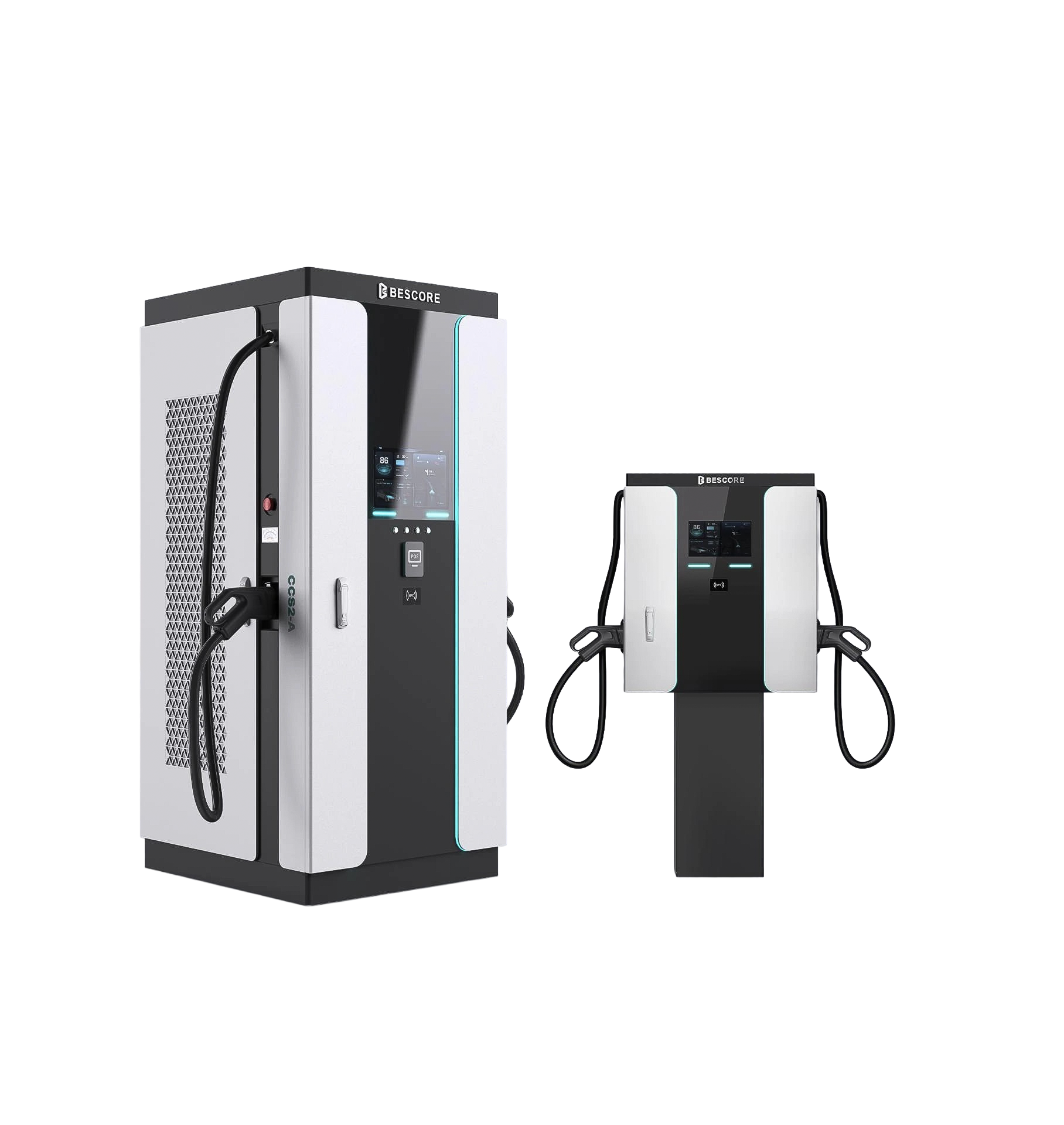
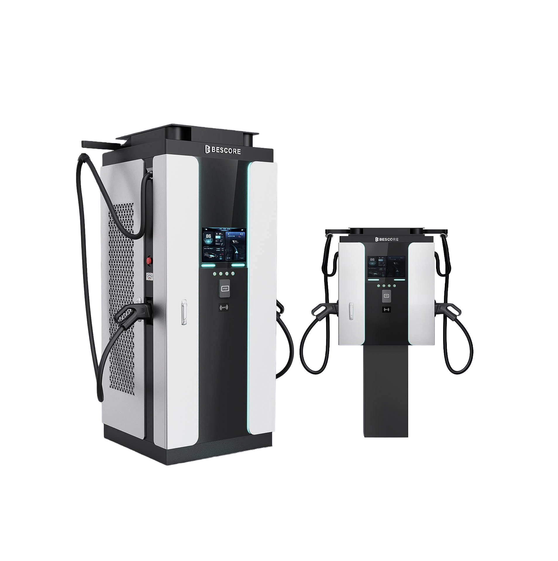 Datasheet-backedFidelity-safe studio treatment
BSC-S03CCN / S06CCC / S08CCC / S12CCC / S16CCC / S18CCC
Documented 30–180kW family.
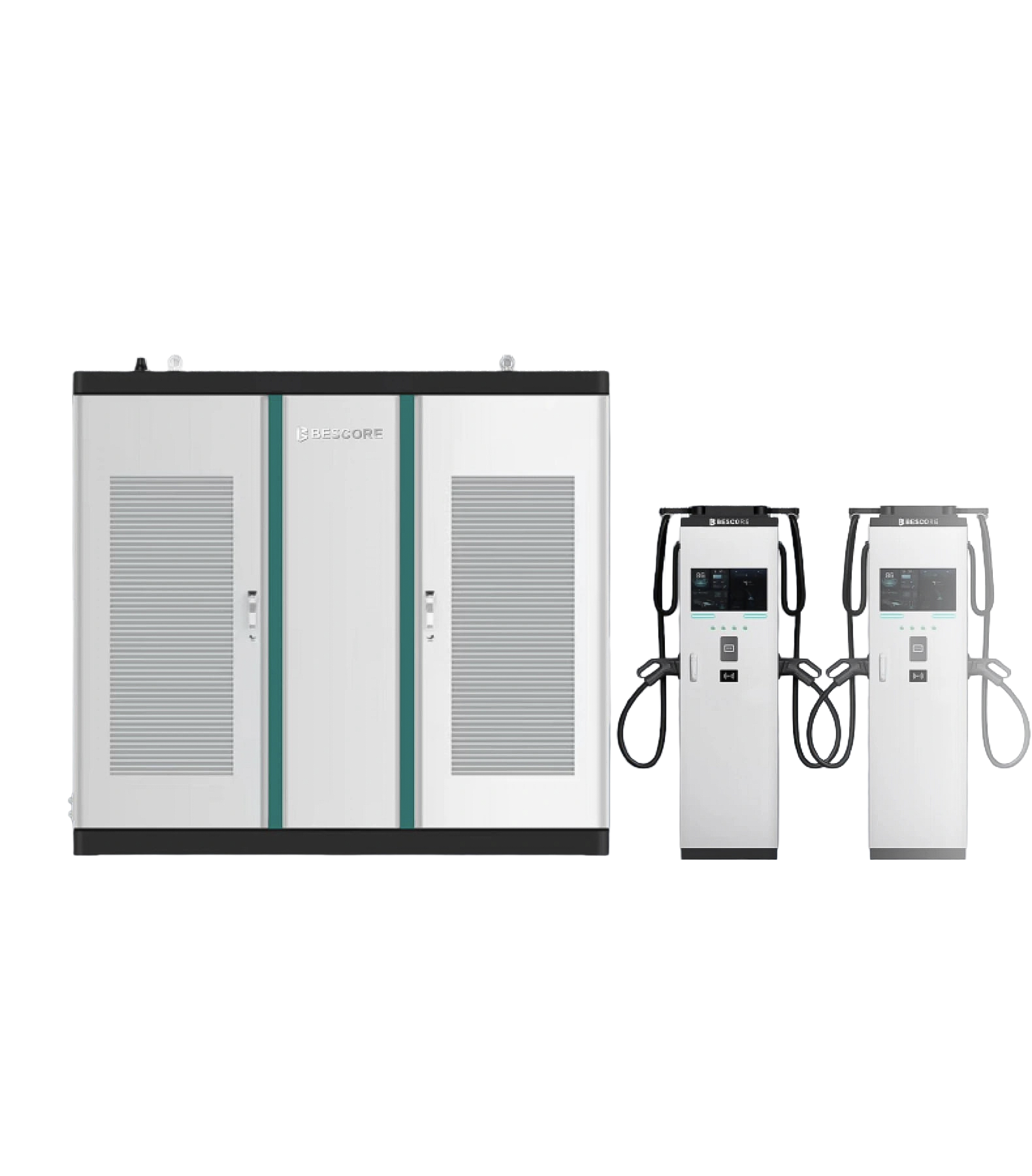
 Datasheet-backedFidelity-safe studio treatment
BSC-S24CCC / S32CCC / S36CCC / S40CCC / S48CCC
Documented 240–480kW family.
 Reconfirm current offerFidelity-safe studio treatment
BSC-F03BC / BSC-F06BCC
30kW and 60kW options previously proposed for cooperative charging hubs.
Transformer upgrades, cabling, switchgear, protection, civil works, permits and demand charges may outweigh charger cost; Metro Power evaluates the whole site.
Move from charger pricing to a whole-site capacity, fleet-service and commercial decision.
Fleet, employees, residents, travelers and public users create different utilization and service expectations.
Define the customer and use case ↗Service capacity, transformer, protection, cable routes, civil works and managed simultaneity set the real limit.
Prepare the site data ↗Utilization, tariff, demand charges, uptime, payment model, civil work and capacity upgrades shape returns.
Model the complete site ↗Connector compatibility, access, OCPP, payment, support, queueing and uptime ownership must be explicit.
Define the operating model ↗Explore connected charger capacity, managed simultaneity and the preliminary site-demand picture.
Start the right conversation