 METRO POWERProduct intelligenceSend a request ↗
EV Charging Infrastructure
BSC-S12BCC / BSC-S18BCC / BSC-S24BCC / BSC-S36BCC
Integrated DC super charger, 120 to 360 kW
Integrated dual-connector DC charger for hubs, fleets and highway sites, published by Bescore as the Super EV charger (EU).
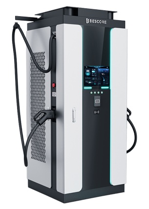
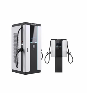
PRODUCT STUDIOBSC-S12BCC / BSC-S18BCC / BSC-S24BCC / BSC-S36BCCProduct image from the available source. Confirm the exact model, ratings, dimensions and interfaces by document.
IMAGE REFERENCEManufacturer product renderThis image supports product identification. Metro Power confirms ratings, dimensions, interfaces and compliance using the applicable documents.
EV Charging Infrastructure
BSC-S12BCC / BSC-S18BCC / BSC-S24BCC / BSC-S36BCCIntegrated DC super charger, 120 to 360 kW
- 01
- 120, 180, 240 or 360 kW maximum output
- 02
- 150 to 1,000 V DC; two CCS2 outlets, 250 A each with a 400 A boost, as stated on the datasheet
- 03
- Open Charge Point Protocol (OCPP) 1.6 JSON; Ethernet, 4G, Wi-Fi, RFID, QR code and card payment terminal
Figures as the principal publishes them. Product image for identification, not an installation.
The charger is the last item on the supply.
The site's transformer and protection set what any charger can deliver. Moving up a power tier usually changes the site before it changes the charger.

Power path
- Utility supplyThe service capacity sets the ceiling.
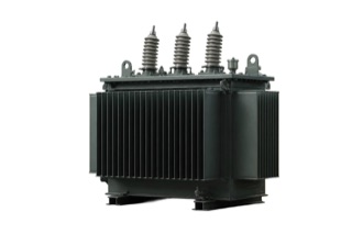
- Site transformerIts rating decides how many chargers run at full power.
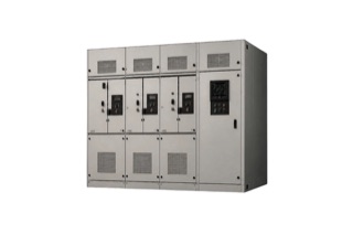
- Switchgear and protectionProtection, earthing and cabling are checked at energisation.
- This productBSC-S12BCC / BSC-S18BCC / BSC-S24BCC / BSC-S36BCCConverts site power to what the vehicle inlet accepts.
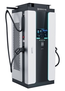
PowerReal product photographDrawn: equipment Metro Power does not supply
Options and differences
Four power tiers, four different sites
Photographs are the principal's product images. The tier follows dwell time and the vehicles on site.
- AC, up to 22 kW
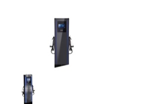
Longer-stay parking. The vehicle's onboard charger sets the speed; a branch circuit usually serves it.
- DC, 30 to 60 kW
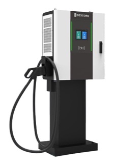
Workplaces, retail and smaller public sites. A three-phase service, checked against the existing load.
- This productDC, 120 to 360 kW
Hubs, fleets and highway sites. Usually a transformer review or a dedicated supply.
- Split DC, 360 to 720 kW
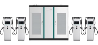
High-throughput sites. A power cabinet feeding separate terminals, each up to 500 kW.
Known product facts
What the current reference supports.
These facts help determine whether the product deserves further review. They are not a complete compliance matrix or project approval.
01 120, 180, 240 or 360 kW maximum output
02 150 to 1,000 V DC; two CCS2 outlets, 250 A each with a 400 A boost, as stated on the datasheet
03 Open Charge Point Protocol (OCPP) 1.6 JSON; Ethernet, 4G, Wi-Fi, RFID, QR code and card payment terminal
04 IP55; -35 to 55 °C; 260 to 475 V AC, 45 to 66 Hz input
Each fact is supported at the evidence level shown above (technical sheet available). Confirm the exact model code, option, revision and controlling terms of reference (TOR) before using any fact in a compliance statement, offer or installation decision.
Professional documentation
One product identity. Five controlled evidence gates.
This schedule shows what the public record supports and what Metro Power must still match before the product becomes a technical or commercial commitment.
ControlCurrent public recordProject release requirementStatus
IdentityBSC-S12BCC / BSC-S18BCC / BSC-S24BCC / BSC-S36BCC · Integrated DC super charger, 120 to 360 kWExact model code, production revision and option scheduleTechnical sheet available
ApplicationIntegrated dual-connector DC charger for hubs, fleets and highway sites, published by Bescore as the Super EV charger (EU).Approved service, duty, site and operating useApplication review
Technical facts120, 180, 240 or 360 kW maximum output · 150 to 1,000 V DC; two CCS2 outlets, 250 A each with a 400 A boost, as stated on the datasheet · Open Charge Point Protocol (OCPP) 1.6 JSON; Ethernet, 4G, Wi-Fi, RFID, QR code and card payment terminal · IP55; -35 to 55 °C; 260 to 475 V AC, 45 to 66 Hz inputControlled datasheet and requirement-by-requirement compliance matrixConfiguration check
Information to prepareVehicle list with each model's DC and AC inlet type and battery voltage class · Energy per vehicle per day and required departure time · Dwell time and turnaround · Transformer/service capacity · Single-line and load profile · Parking, trenching and cable routes · Permits, payment and operating model · Earthing arrangement and available protection at the supply boardDrawings, terminals, communications, accessories and system interfacesEvidence required
Approval and supplyNot shown on this pageCurrent certificates, test records, principal confirmation, availability and deliveryRelease before offer
An image starts identification. Controlled evidence completes selection.
Application context
Where this product family may enter the system.
Application fit depends on the exact service, duty, operating objective and approved configuration. Use these as discovery prompts, not automatic recommendations.
Configuration gate
What must be confirmed before an offer.
Transformer upgrades, cabling, switchgear, protection, civil works, permits and demand charges may outweigh charger cost; Metro Power evaluates the whole site. The connector family is fixed by the vehicles, not by preference, and is confirmed from the fleet survey before any charger is proposed.
Understand the complete system architecture ↗- 01Vehicle list with each model's DC and AC inlet type and battery voltage class
- 02Energy per vehicle per day and required departure time
- 03Dwell time and turnaround
- 04Transformer/service capacity
- 05Single-line and load profile
- 06Parking, trenching and cable routes
From product interest to a controlled offer.
Requirement
Confirm the operating need, service, site and controlling specification.
Configuration
Match ratings, options, communications, interfaces and accessories.
Evidence
Check datasheet revision, compliance, certificates and confirmation gaps.
Offer gate
Release price and delivery only against the approved configuration.
Related within EV Charging Infrastructure
Compare before you narrow.
Adjacent products may serve different ratings, service arrangements or operating requirements. Open each record or use the portfolio comparison tool.
01Availability needs checking22 kW / dual 22 kWAC destination charger↗02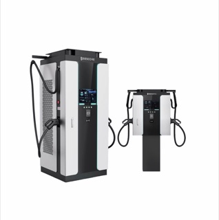 Availability needs checkingBSC-S03CCN / S06CCC / S08CCC / S12CCC / S16CCC / S18CCCIntegrated DC fast charger↗03
 Availability needs checkingBSC-S24CCC / S32CCC / S36CCC / S40CCC / S48CCCIntegrated ultra-fast charger↗
Compare the EV Charging Infrastructure portfolio ↗Availability needs checking22 kW / dual 22 kWAC destination charger↗02Availability needs checkingBSC-S03CCN / S06CCC / S08CCC / S12CCC / S16CCC / S18CCCIntegrated DC fast charger↗03Availability needs checkingBSC-S24CCC / S32CCC / S36CCC / S40CCC / S48CCCIntegrated ultra-fast charger↗CONTROLLED DOCUMENT REQUEST
Send a request ↗Need the current datasheet or compliance evidence?
Metro Power will match the document revision, model and configuration to your requirement before release. Tell us the decision, TOR or application the document must support.