 METRO POWERProduct intelligenceSend a request ↗
BESS & Microgrids
BSC-CF2-0050K0100K-H
PV, storage and hybrid inverter cabinet
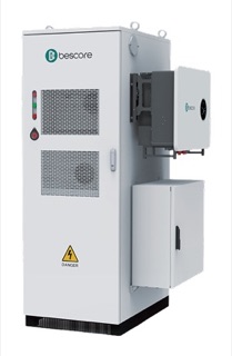
Outdoor all-in-one cabinet combining a hybrid inverter, battery and solar input for small commercial microgrids and backup. Published by Bescore as the CF2-50 in three sizes.
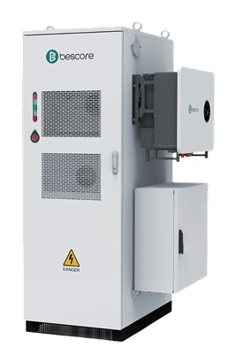
PRODUCT STUDIOBSC-CF2-0050K0100K-HProduct image from the available source. Confirm the exact model, ratings, dimensions and interfaces by document.
IMAGE REFERENCEManufacturer product renderThis image supports product identification. Metro Power confirms ratings, dimensions, interfaces and compliance using the applicable documents.
BESS & Microgrids
BSC-CF2-0050K0100K-HPV, storage and hybrid inverter cabinet
- 01
- 50 kW with 100 kWh (this model), 40 kW with 86 kWh (BSC-CF2-0040K0080K-H) or 30 kW with 71 kWh (BSC-CF2-0030K0060K-H)
- 02
- Rated 50 Hz as published by Bescore; a 60 Hz version for the Philippine grid is not yet confirmed
- 03
- Solar input up to 60, 80 or 100 kWp; LFP cells, 280 Ah
Figures as the principal publishes them. Product image for identification, not an installation.
What the storage system connects to.
A battery only earns its place through the equipment around it: the supply it charges from, the switchgear that isolates it, the loads it protects and the sources a controller must coordinate.
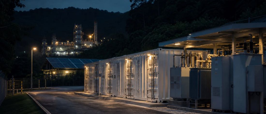
Power path
- Utility gridAbsent on an off-grid site.
- TransformerService transformer, or an isolation transformer for an island.
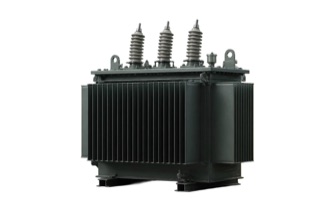
- Switchgear and transfer deviceIsolates the system and moves the site between grid and island.
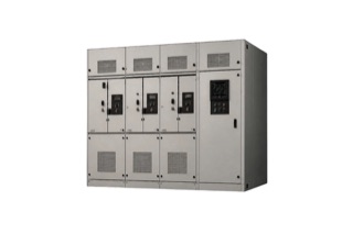
- This productBSC-CF2-0050K0100K-HStores energy as DC and delivers it through the PCS.
- Site loadsCritical loads first when the battery is the only source.
Other sources the controller coordinates
- SolarCharges the battery or serves load directly.
- Diesel generatorBackup, or the second source on an island.
- From the BSC-CF2-0050K0100K-HDispatch rules decide which source serves which load.
PowerReal product photographDrawn: equipment Metro Power does not supply
Options and differences
From pack to power station, as the principal publishes them
Storage is built in steps. Each step adds energy, voltage and the equipment needed to connect it.
- Battery pack
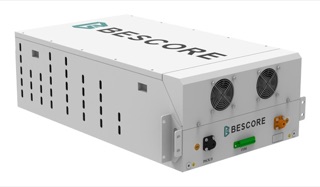
14 kWh at 51.2 V DC. The building block.
- Battery rack
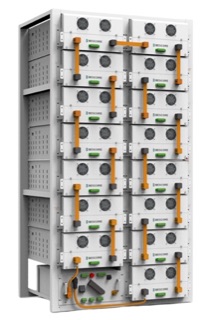
215 kWh at 768 V DC. Packs in series, fitted inside an enclosure.
- Cabinet system
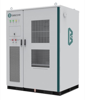
105 kW with 215 kWh. Battery, PCS and controls in one outdoor cabinet.
- Battery compartment
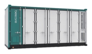
Up to 5,016 kWh at 1,331.2 V DC. DC only; converts in a separate station.
- PCS and MV station
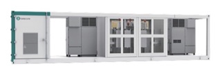
Up to 5,000 kW, stepped up to 10, 20 or 35 kV.
Known product facts
What the current reference supports.
These facts help determine whether the product deserves further review. They are not a complete compliance matrix or project approval.
01 50 kW with 100 kWh (this model), 40 kW with 86 kWh (BSC-CF2-0040K0080K-H) or 30 kW with 71 kWh (BSC-CF2-0030K0060K-H)
02 Rated 50 Hz as published by Bescore; a 60 Hz version for the Philippine grid is not yet confirmed
03 Solar input up to 60, 80 or 100 kWp; LFP cells, 280 Ah
04 IP55 cabinet; air-cooled; 10 ms grid-to-backup switching, as stated on the datasheet
Each fact is supported at the evidence level shown above (technical sheet available). Confirm the exact model code, option, revision and controlling terms of reference (TOR) before using any fact in a compliance statement, offer or installation decision.
What is inside the BSC-CF2-0050K0100K-H.
The blocks, the power path and the four signal buses, redrawn from the principal's published circuit diagram. It shows arrangement, not wiring; installation follows the controlled drawings.
Arrangement drawing
Inside the CF2-50 hybrid cabinet
Redrawn by Metro Power from the circuit diagram Bescore publishes for the CF2-50. Principal's published figures.How to read it
- One battery string feeds one hybrid inverter with four ports: load, generator, grid and solar.
- Grid and generator are separate inverter ports, so the choice of source is made inside the inverter.
- Temperature, alarm and fire are hard-wired into the BCMU rather than passed as software messages.
- The distribution box that fans out to load, generator and grid is drawn outside the supplied cabinet.
Key
- DC power
- AC power
- CAN bus: battery data
- RS485: auxiliaries
- IO: hard-wired safety signals
- LAN or Ethernet
- Monitoring connection
- Energy flow, shown when motion is allowed
BMU: battery management unit, one per module. BCMU: battery cluster management unit, one per string. HV box: DC contactors and fuses between the string and the converter.
LCU is printed without an expansion on the principal's drawing. Metro Power confirms its function before describing it.
Professional documentation
One product identity. Five controlled evidence gates.
This schedule shows what the public record supports and what Metro Power must still match before the product becomes a technical or commercial commitment.
ControlCurrent public recordProject release requirementStatus
IdentityBSC-CF2-0050K0100K-H · PV, storage and hybrid inverter cabinetExact model code, production revision and option scheduleTechnical sheet available
ApplicationOutdoor all-in-one cabinet combining a hybrid inverter, battery and solar input for small commercial microgrids and backup. Published by Bescore as the CF2-50 in three sizes.Approved service, duty, site and operating useApplication review
Technical facts50 kW with 100 kWh (this model), 40 kW with 86 kWh (BSC-CF2-0040K0080K-H) or 30 kW with 71 kWh (BSC-CF2-0030K0060K-H) · Rated 50 Hz as published by Bescore; a 60 Hz version for the Philippine grid is not yet confirmed · Solar input up to 60, 80 or 100 kWp; LFP cells, 280 Ah · IP55 cabinet; air-cooled; 10 ms grid-to-backup switching, as stated on the datasheetControlled datasheet and requirement-by-requirement compliance matrixConfiguration check
Information to prepare12 months of bills and tariff · Interval load data · Critical loads and outage history · Solar/generator details · Single-line and transformer data · Site, fire and interconnection constraints · Service voltage and frequency (the Philippine grid is 60 Hz) · Existing solar: inverter make, rating and how it connects · The largest motor that must start in an island, with its starting current · Distance to the coast and exposure to salt airDrawings, terminals, communications, accessories and system interfacesEvidence required
Approval and supplyNot shown on this pageCurrent certificates, test records, principal confirmation, availability and deliveryRelease before offer
An image starts identification. Controlled evidence completes selection.
Application context
Where this product family may enter the system.
Application fit depends on the exact service, duty, operating objective and approved configuration. Use these as discovery prompts, not automatic recommendations.
Configuration gate
What must be confirmed before an offer.
Capacity, savings and backup duration require validated interval load, site and operating data; monthly consumption alone is insufficient. Frequency, service voltage and the largest motor to be started are confirmed before any model is proposed.
Understand the complete system architecture ↗- 0112 months of bills and tariff
- 02Interval load data
- 03Critical loads and outage history
- 04Solar/generator details
- 05Single-line and transformer data
- 06Site, fire and interconnection constraints
From product interest to a controlled offer.
Requirement
Confirm the operating need, service, site and controlling specification.
Configuration
Match ratings, options, communications, interfaces and accessories.
Evidence
Check datasheet revision, compliance, certificates and confirmation gaps.
Offer gate
Release price and delivery only against the approved configuration.
Related within BESS & Microgrids
Compare before you narrow.
Adjacent products may serve different ratings, service arrangements or operating requirements. Open each record or use the portfolio comparison tool.
01Technical sheet availableBSC-CE2-0105K0215K / BSC-CE2-0105K0200KAir-cooled microgrid ESS↗02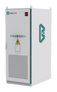 Technical sheet availableBSC-CE4-0125K0261KLiquid-cooled C&I ESS↗03
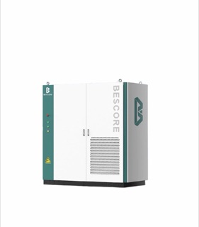 Availability needs checkingBSC-CD2-0050K0200KPV + diesel + storage ESS↗
Compare the BESS & Microgrids portfolio ↗Technical sheet availableBSC-CE2-0105K0215K / BSC-CE2-0105K0200KAir-cooled microgrid ESS↗02Technical sheet availableBSC-CE4-0125K0261KLiquid-cooled C&I ESS↗03Availability needs checkingBSC-CD2-0050K0200KPV + diesel + storage ESS↗CONTROLLED DOCUMENT REQUEST
Send a request ↗Need the current datasheet or compliance evidence?
Metro Power will match the document revision, model and configuration to your requirement before release. Tell us the decision, TOR or application the document must support.